Instructions
Using the interface
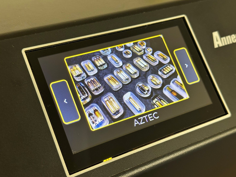
When turning on the machine the mode select screen will show. To navigate between different modes, simply tap the arrow button on the left and right of the screen to change between modes and then tap the middle of the screen to enter the desired mode.
Once you have entered a mode at any time you can press the “Back” button in the top left corner of the screen to go back one page.
Selecting the pilot
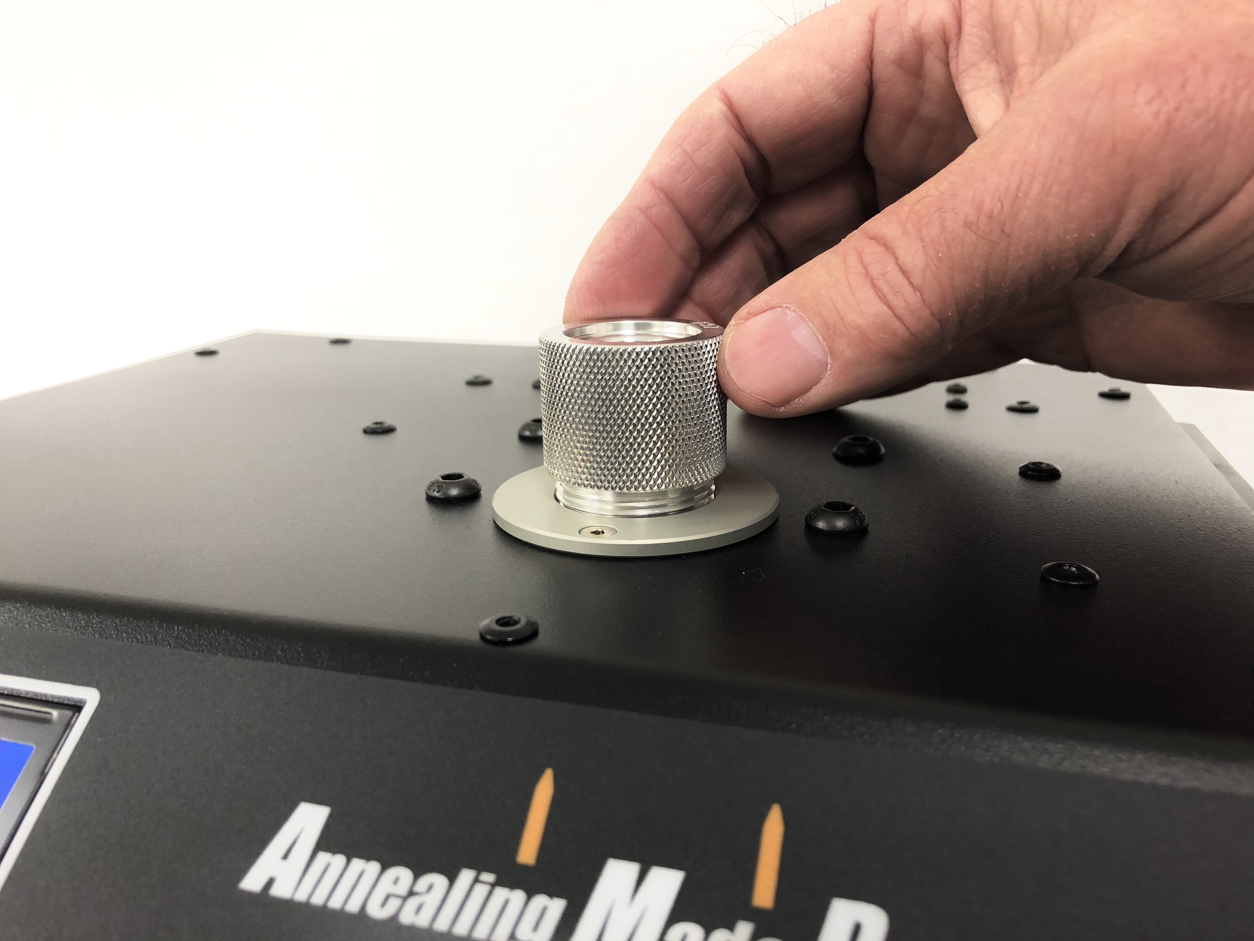
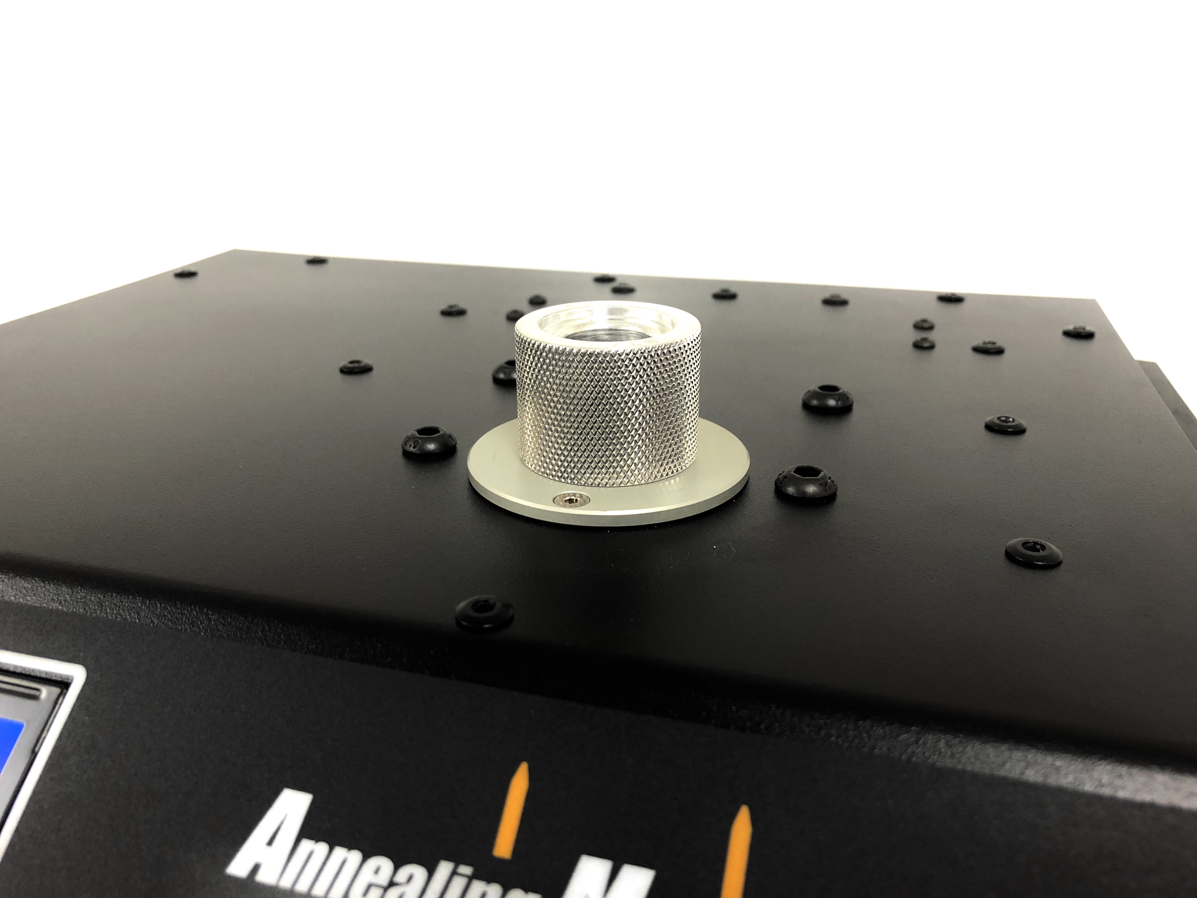
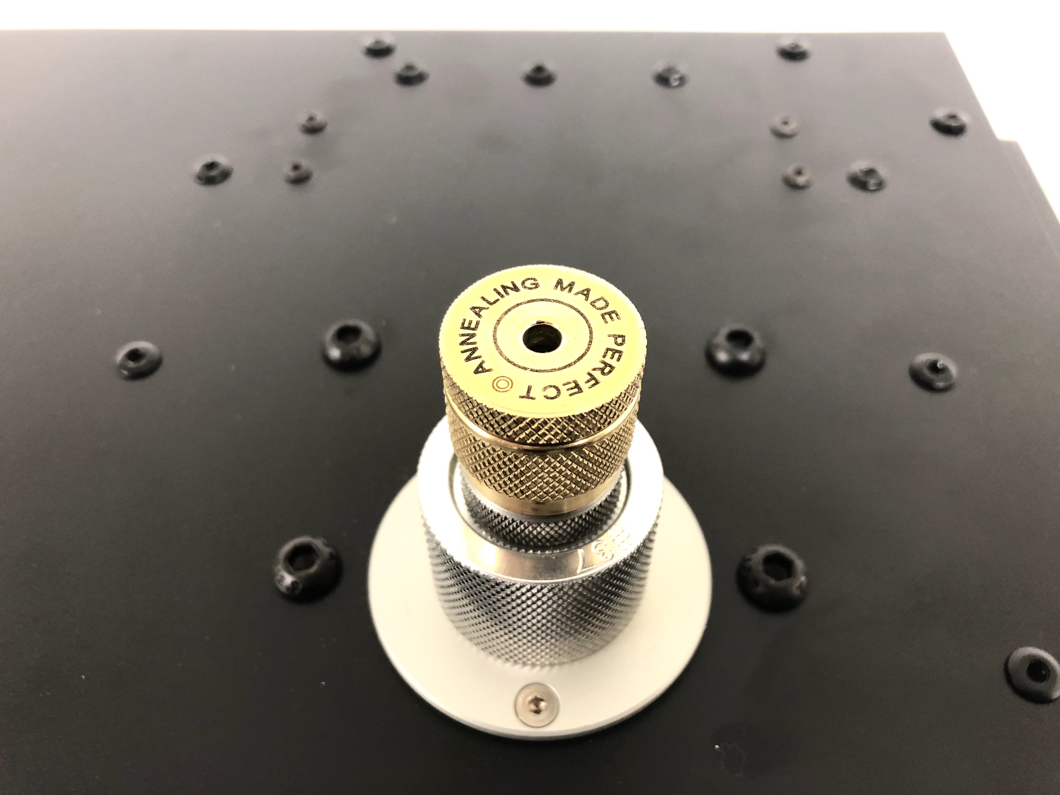
When selecting the correct pilot to use for any cartridge, refer to the 'Settings and Pilots” page on the website, where the correct pilots for all cartridges are listed. Some pilots can be used for multiple cartridges. Insert the correct aluminium pilot into the boss on the machine until it has bottomed out. Do not over tighten. Take care to avoid cross threading the pilot when inserting as damage to the boss plate female thread may result.
Operating MODES
AZTEC:
Basic operation and selecting a function
AZTEC is self-prompting and very simple to use with minimal technical expertise.
When entering AZTEC mode you have two options. ANALYSE and RUN.
ANALYSE is used in order to analyse a single from the batch you wish to annealer in order to generate an annealing setting based off that case. The case is sacrificed in the process and should be discarded after. RUN mode allows you to enter a saved setting or to manually enter one in order to anneal a batch of cases.
Analysis mode
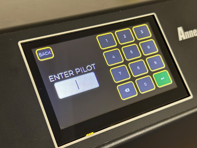
When entering ANALYSIS mode you will be prompted to enter the pilot for the case you wish to anneal. Refer to our website under Settings/Pilot > AZTEC for the pilot and Suffix combination for your cartridge case.

For example here we are going to enter Pilot #11.
Press the green arrow button to enter that pilot and advance to the Suffix screen.
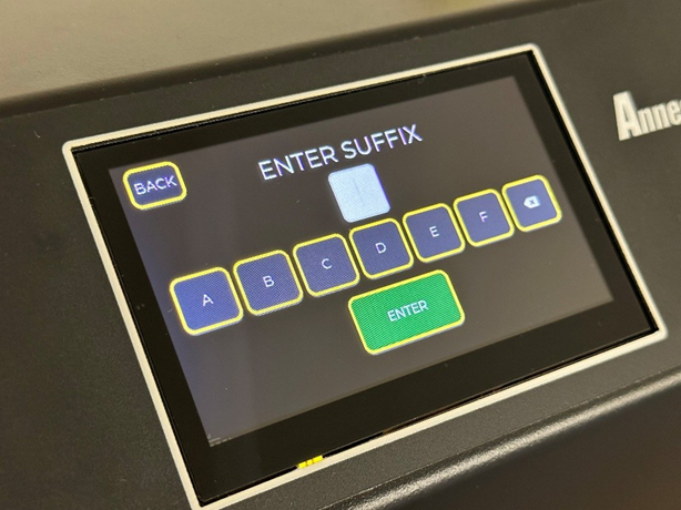
Once the Pilot number is entered the Suffix screen is displayed. Enter the correct suffix for your cartridge case after consulting the AZTEC settings page of our website. Note that different cases that use the same Pilot in many instances will need a different suffix to analyse correctly.

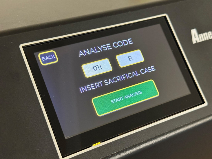
Once you have entered the Pilot and Suffix the ANALYSIS CODE page will display showing what you have entered. You can now insert the case to be analysed and then press START ANALYSIS to begin the analysis process.
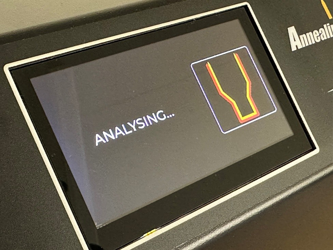
When the case is being analysing the display will show the above graphic.
Ensure that you do not remove the case during this process.
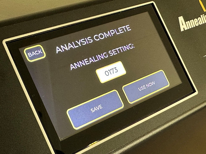
Once the Analysis is completed the generated code will display. You will have the option to either SAVE or USE NOW. You can now safely remove the case and discard it. CAUTION: The case will be EXTREAMLY HOT, Take care when removing it and discarding it!
Entering USE NOW will load that setting and take you to the RUN screen.
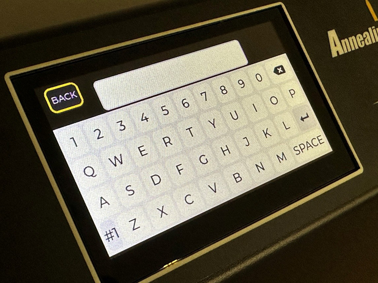
When entering SAVE a keypad will appear where you can name your setting and then press the arrow (Enter) button above the SPACE bar to save it into the DATABASE to be recalled later.
RUN MODE
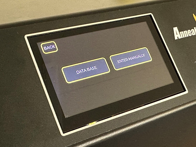
When entering RUN MODE two options will appear. DATABASE or ENTER MANUALLY.
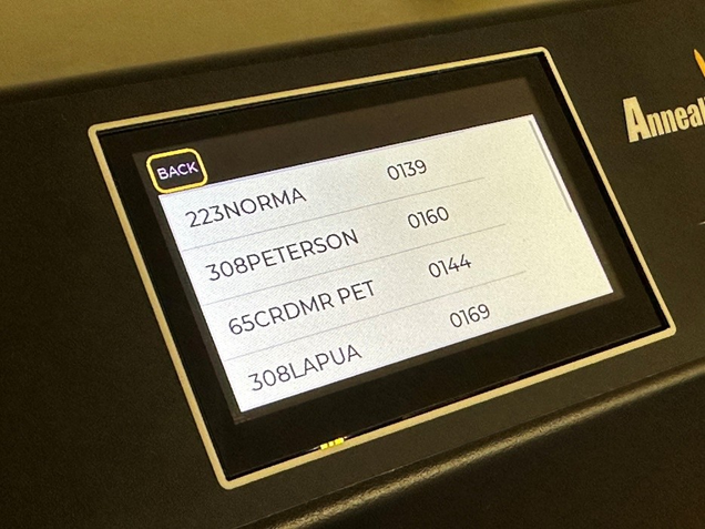
When entering the DATABASE you can scroll through your previously loaded settings.
Tapping a setting will show a pop up window asking if you want to load, cancel or delete a setting.
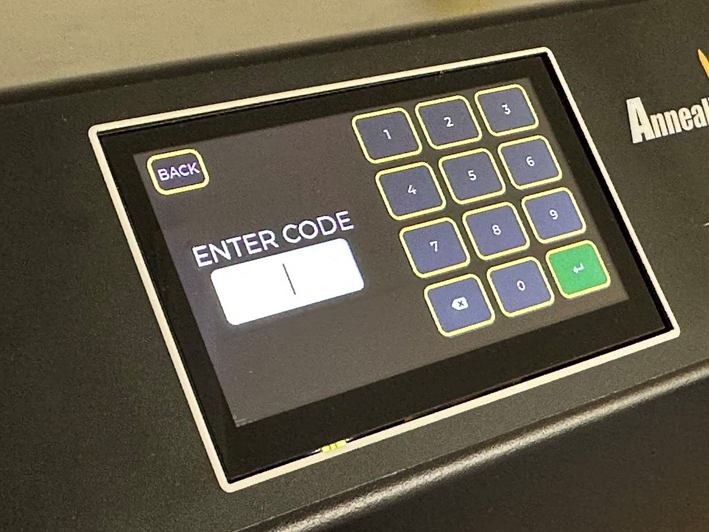
If ENTER MANUALLY is selected you can enter the desired setting using the keypad. Note that STANDARD mode settings are NOT compatible with AZTEC settings.
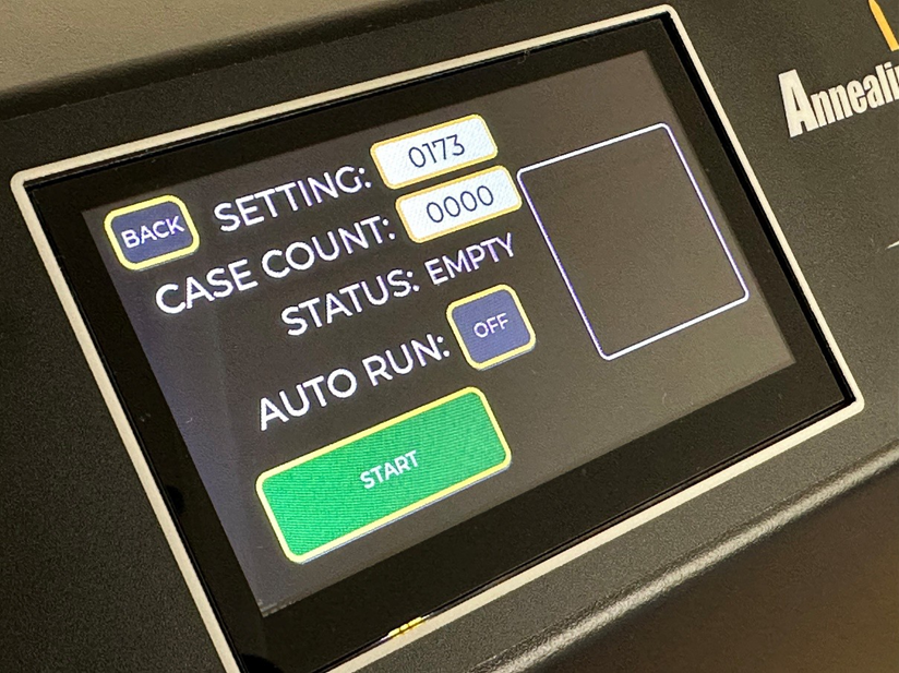
When USE NOW is selected or if you have loaded a setting from the DATABASE or entered it manually the RUN screen will appear. It shows the following features:
Setting: The currently loaded annealing setting
Case count: The number of cases annealed in the current session
Status: The status of the annealer being either Empty, Ready, Annealing or Done
Auto Run: Toggle either on or off and will automatically start the annealing cycle if a case is inserted.
START: Will start the annealing cycle if tapped once a case is inserted. Is disabled if Auto run is enabled.
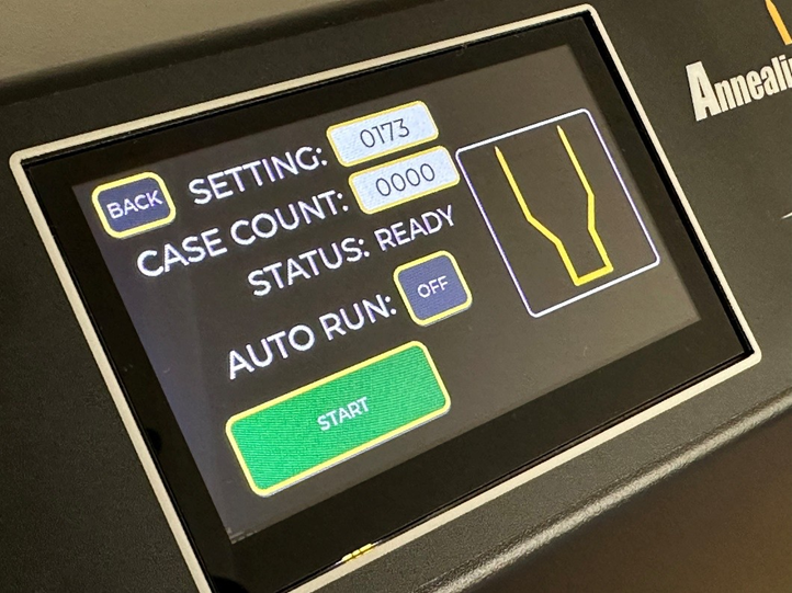
When a case is inserted into the pilot to be annealed, the annealer will detect the case and then update the status as well as display a graphic in the graphic window.
If auto run is enabled (ON) then at this point the annealing process will start If it is turned off then pressing START will start the annealing process.
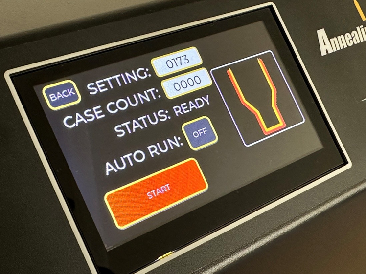
When the annealing cycle starts the Graphic will change to red as well as the start button being illuminated red. The Status will also change to ANNEALING. Ensure that you do not remove the case during the annealing process.
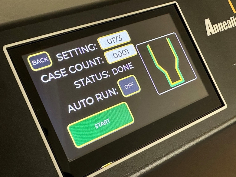
Once the annealing cycle has completed the CASE COUNT will go up by one and the Status will change to Done. The graphic and Start button will also change to Green. You can now safely remove the case and place it into your cooling tray. Please note that cases will be VERY HOT after being annealed.
Selecting the sacrificial case
It is important that the sacrificial case is representative of the cases you are going to anneal. The two most significant factors are neck wall thickness and case weight. If cases have been accurately neck turned that makes the task simple. If not, use a ball micrometer to check neck wall thicknesses. We suggest checking say ten cases and selecting an average representative.Ensure that the case necks and mouths are round. Out-of-round necks will generate erratic codes.
For more detail on this process click here
There is some debate about the merits of sorting cases by weight for competition shooting. We can’t comment on the benefits or otherwise on downrange accuracy, but we have found that case weight affects the correct annealing setting more often than not. We always sort customer samples for case weight as part of our laboratory procedure when calibrating standard program settings. You don’t need the most sophisticated scales for this task. We use a simple digital scale accurate to 0.1 g. We are not looking for tiny variations. We treat anything over 0.5 gr. as potentially significant. Two grains or more will frequently affect the annealing outcome. For hunting cases the difference is inconsequential. For competition, every bit matters.
Provided the brass is generally of good quality, there will be minimal variation in annealing across a whole batch if the best median case is selected as the sacrifice. With match quality turned and sorted brass there should be virtually no annealed variation.
We recommend that the sacrificial case should be fire formed and unsized. That is when cases should be annealed in the reloading cycle. There can be minor but significant differences in the code which AZTEC will allocate between sized and unsized cases.
We have found no difference in the code allocation using clean or dirty cases. We have also found that trim to length dimensions (within reason) have no effect on the code allocation.
Advanced Functions
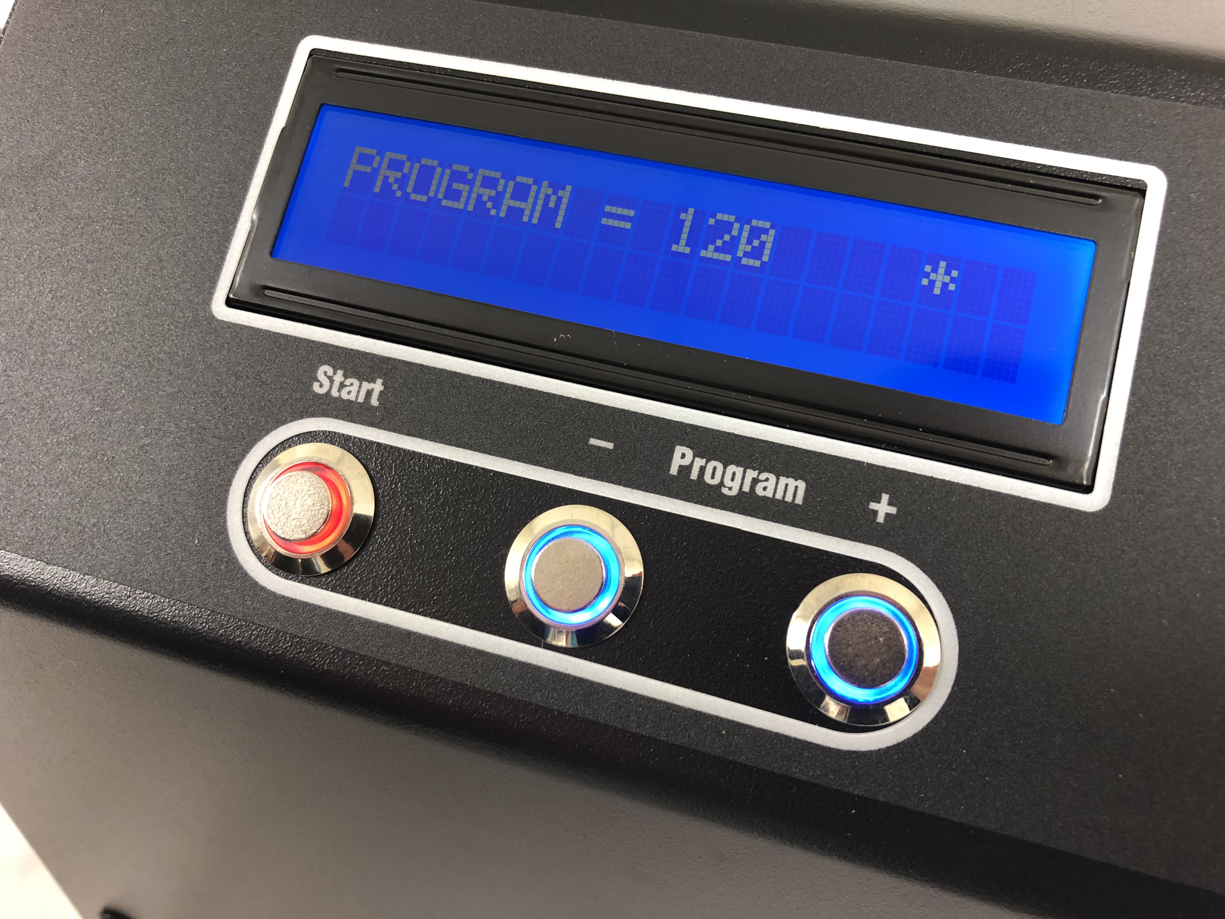
As mentioned in "Analysis mode”, after a sacrificial case is analysed and USE is entered, the display will show RUN with a 0 and a * program lock to the right. The 0 gives the user that ability to customise their annealing even further.
To access the 0, firstly the * program lock must be opened. Just hold down the + button for two seconds and the * will disappear. Now the +/- buttons can be used to select up to six incremental adjustments up or down. + = more power = softer. These adjustments have been calibrated to give the same annealed hardness (HV) increments regardless of the cartridge. This means that the HV value per step is the same for say a 22 Hornet or a 338 Lapua Magnum. Each step represents approx. 2.5 HV, so that four steps will give approx. 10 HV up or down.
We always recommend that the ANALYSE generated code is used, because in our opinion it gives the optimal neck and shoulder annealed hardness. We do understand however that many reloaders will appreciate the ability to experiment.
Standard:
Select Standard mode and press Start to enter. When selecting the correct program to use, refer to the ‘Settings and pilots’ tab on our website and select STANDARD. The correct programs for all the cartridges we have tested are listed.
Programs are generally based on three things: Caliber, Brand and neck wall thickness. Ensure you choose the correct program based on your cartridge.
My Cartridge is not listed?
With AZTEC mode, the only time you would need to send samples to us is if the cartridge or Wildcat is completely new to our system. Then we need samples to set the correct AZTEC pilot code for that cartridge. Once that has been done, AZTEC will handle all variations of that cartridge, such as different brands or neck wall thickness.
If you are using STANDARD mode and the cartridge is not listed a sample will need to be sent to us to for analysis in order to create a setting and pilot for it. The STANDARD settings page has info on how to send us samples.
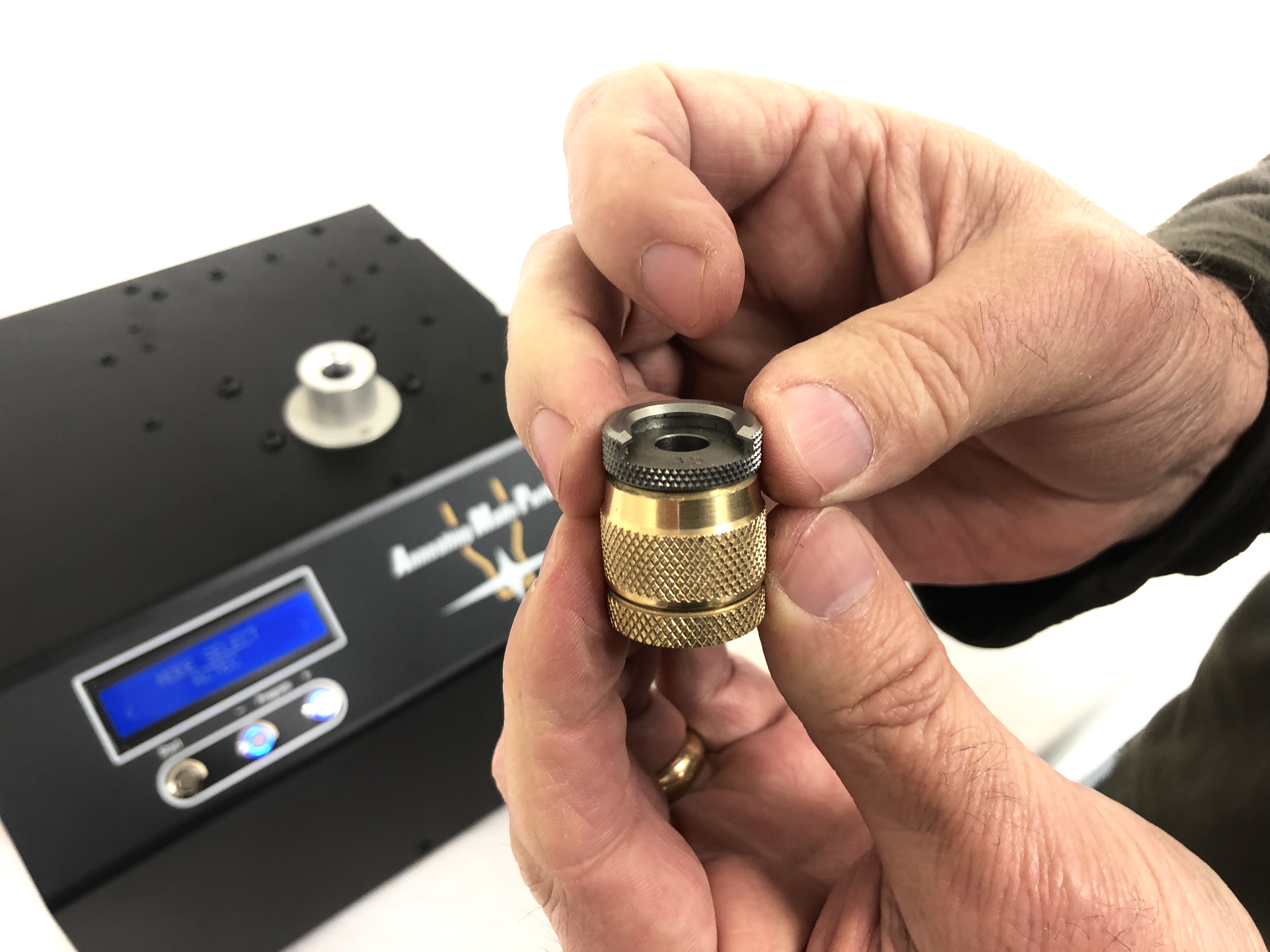
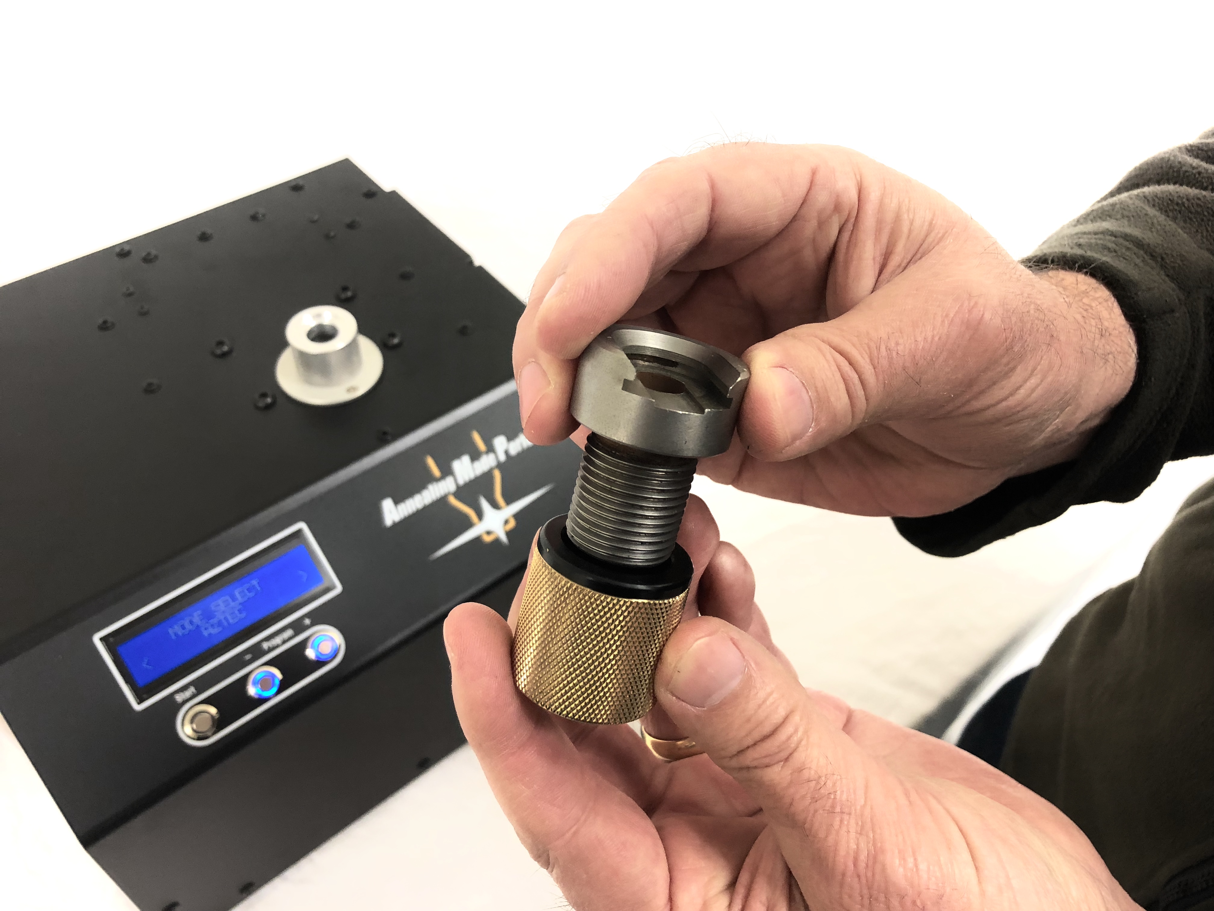
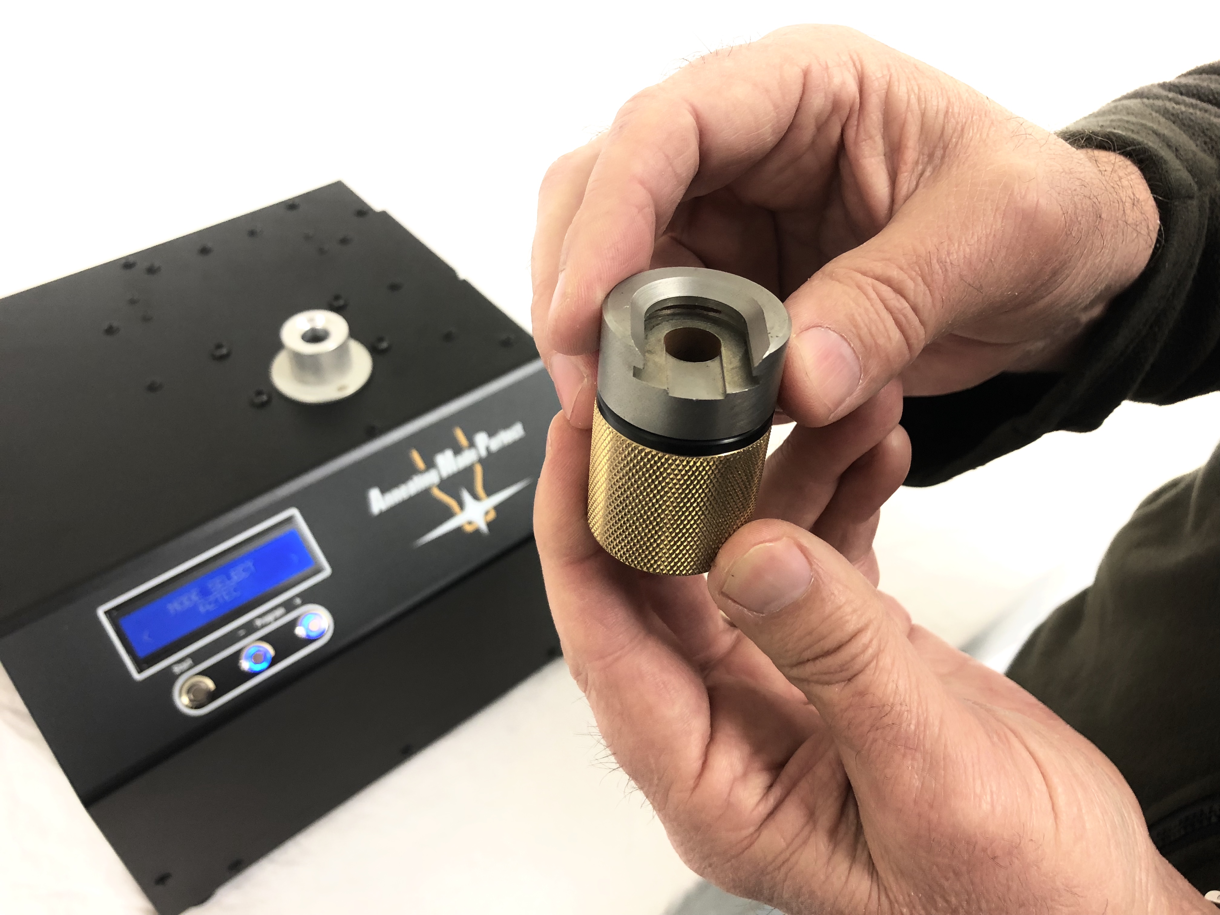
Shell Holder Grip
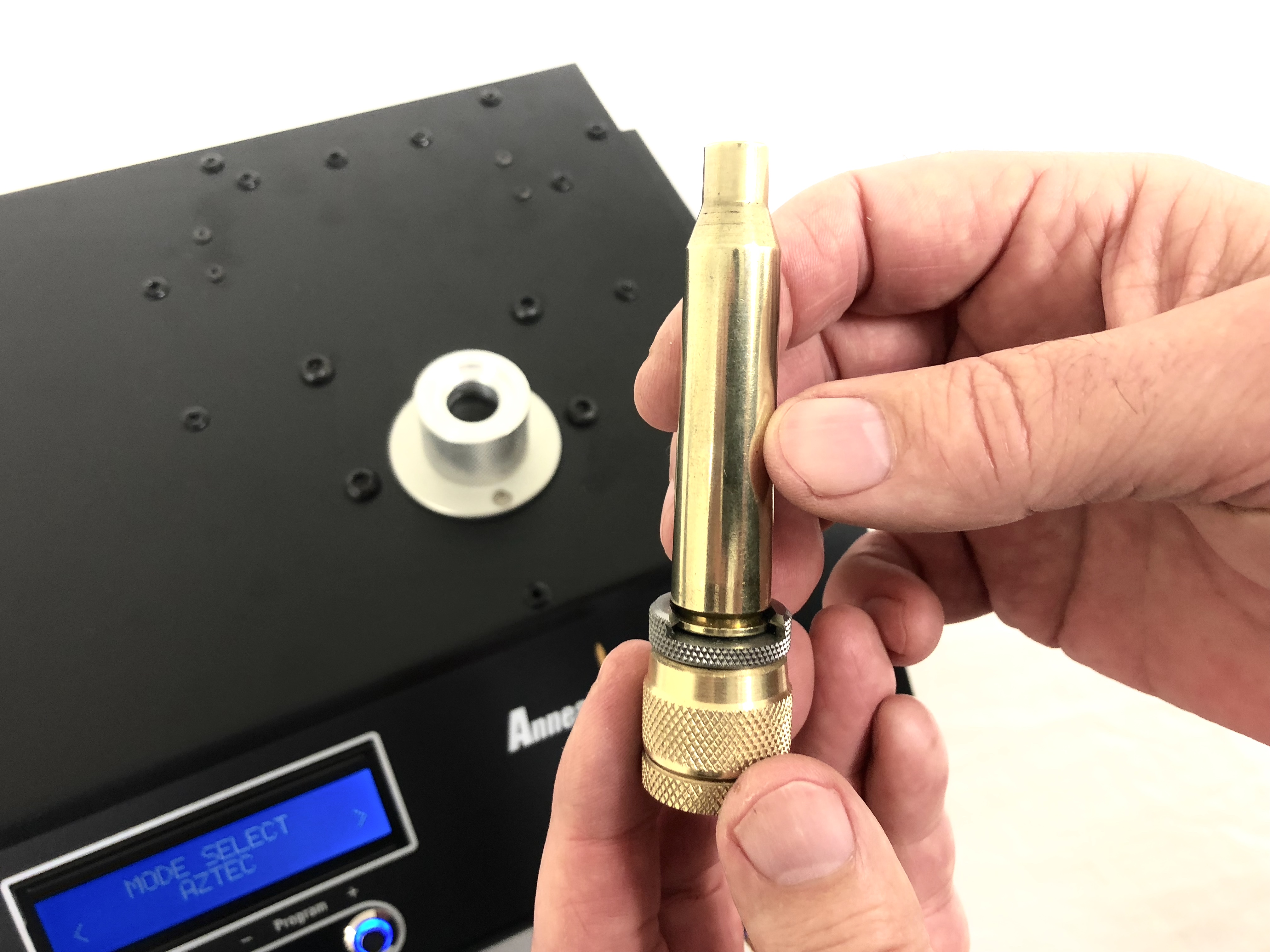
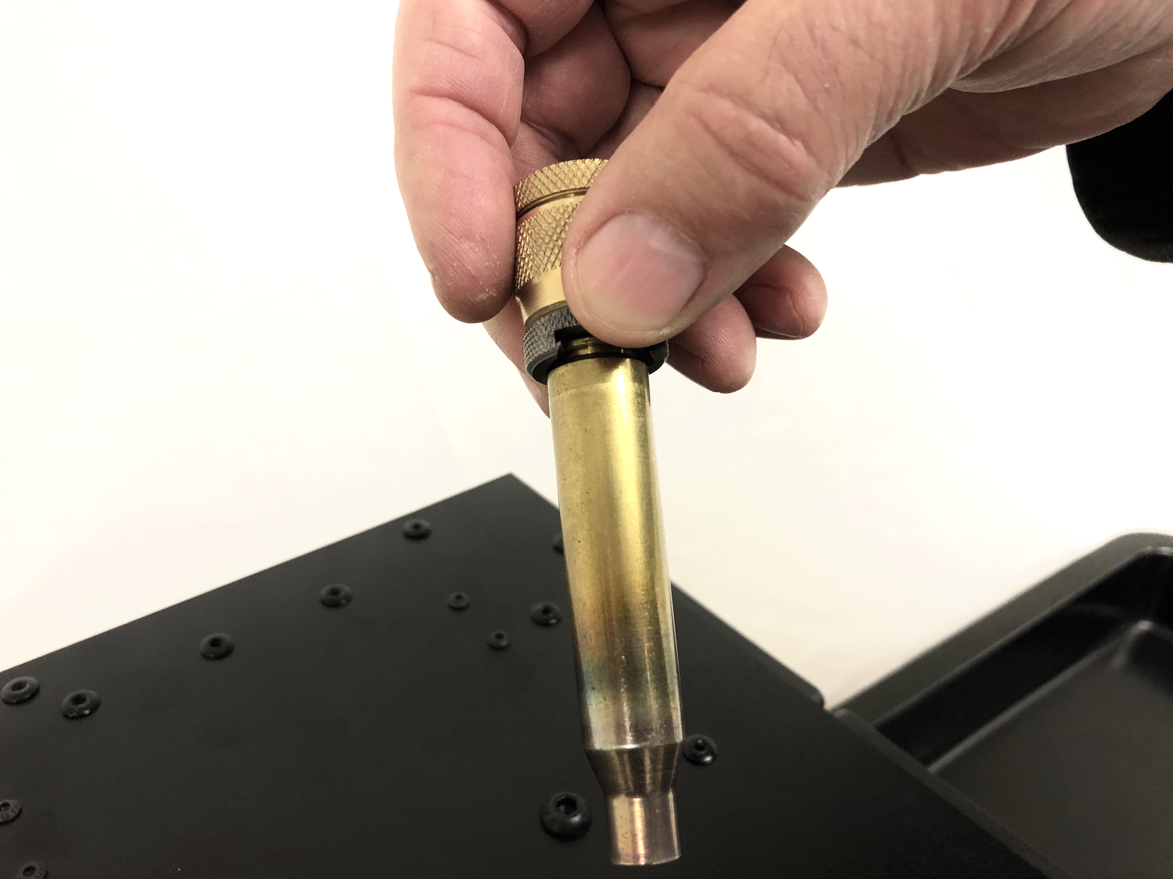
Your cartridge specific shell holder is used to insert the cartridges into the machine. A custom brass grip for standard shell holders is provided with each annealer. This attaches to the shell holder to make it more comfortable to use. Insert the shell holder lug end into the grip and tighten the collet. The 50 BMG pilot grip is threaded and insulated to prevent heating. It is sold separately.
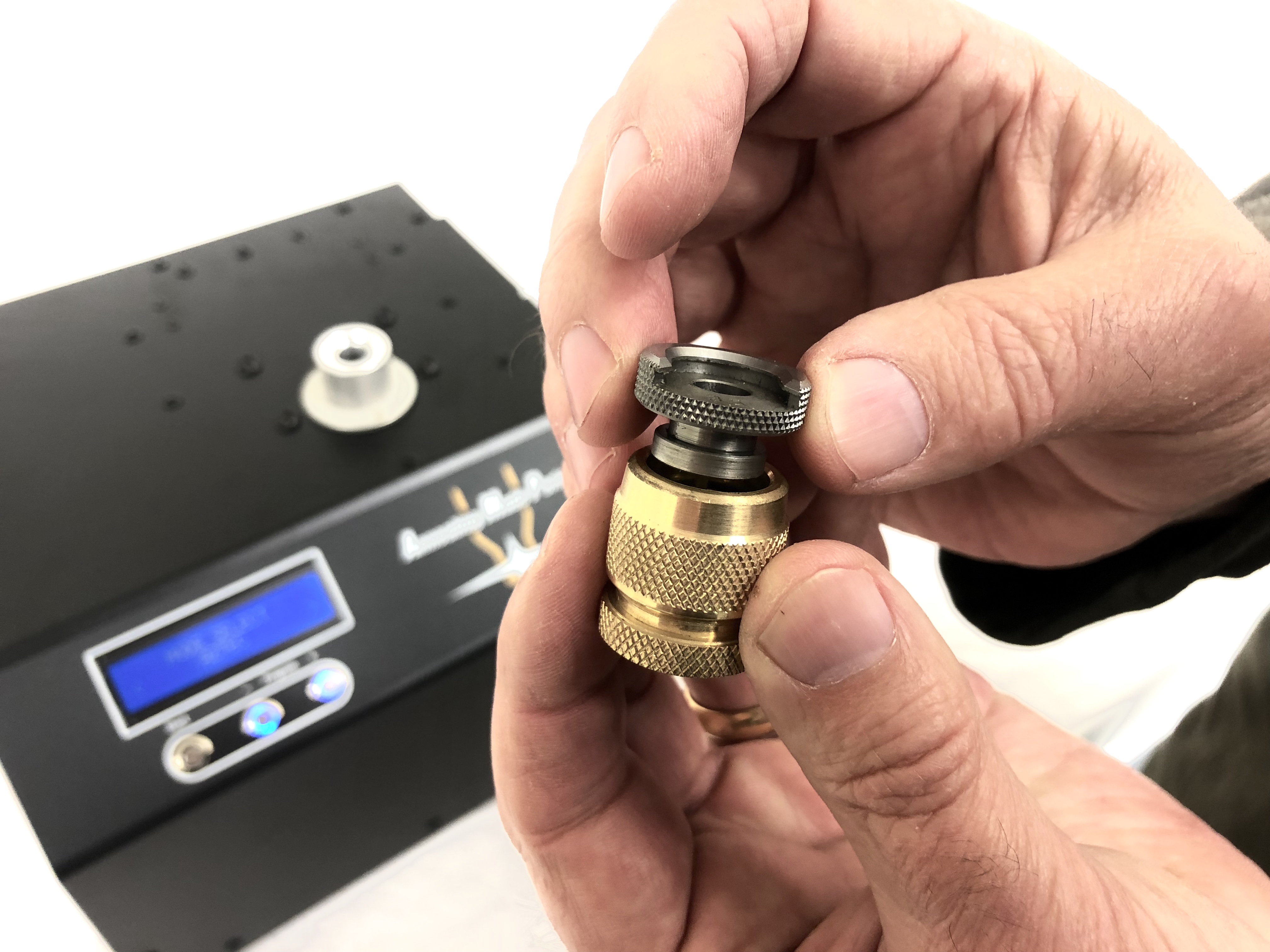
Shell holders not supplied. All common brands of standard shell holders as used in reloading presses will fit into the brass grip. We get the best results with Redding EZ feed, in particular if using the AMP MATE auto feeder. 50 Cal shell holder brass grip sold separately.
Using the machine
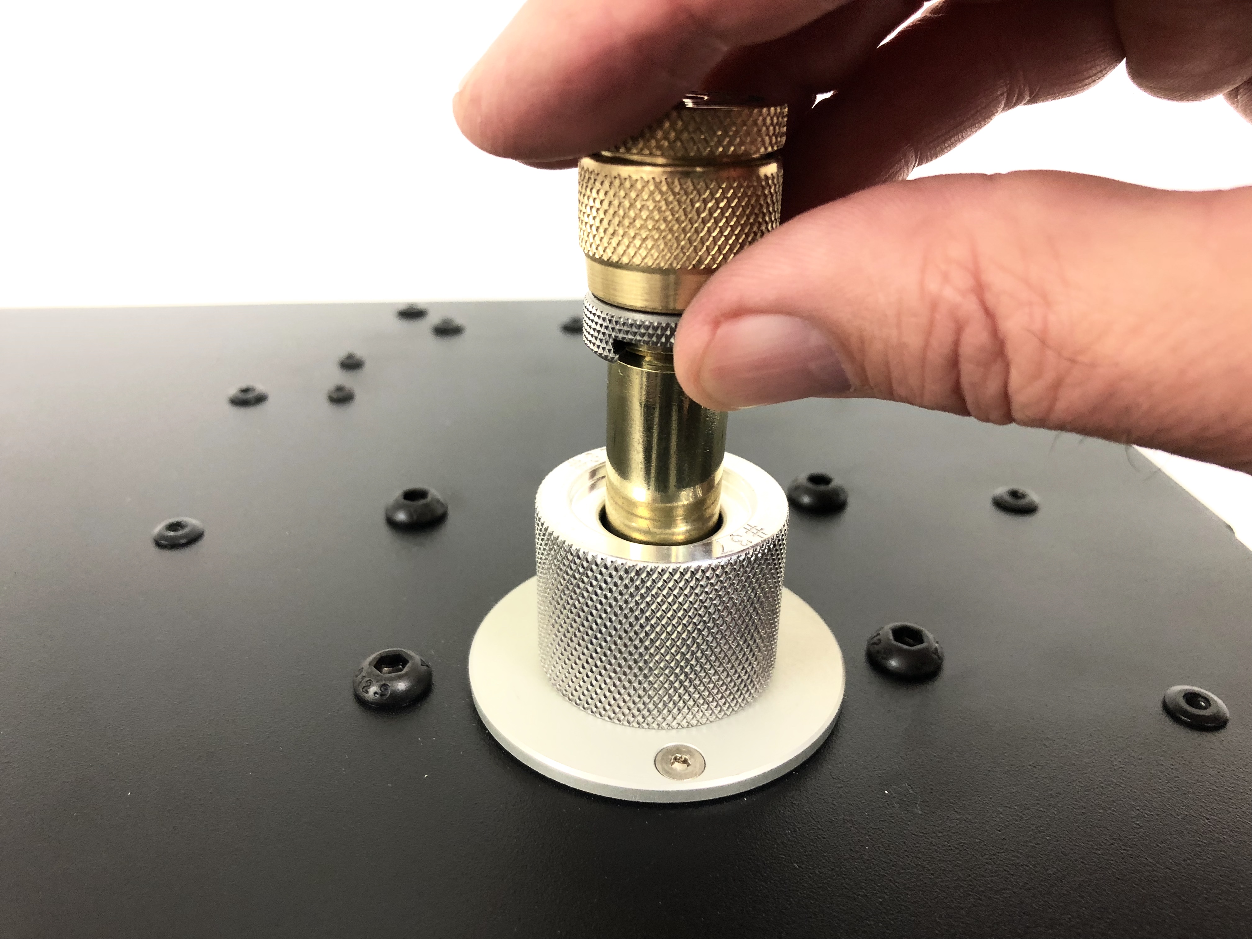
With the correct pilot fitted, and the correct Standard program or AZTEC code loaded in the machine annealing can now commence. Place a cartridge into the shell holder/grip combination and insert the cartridge into the pilot. Make sure the face of the shell holder is mated square to the face of the pilot.
Press the start button to anneal. The button will illuminate red during heating and will turn off when finished.
Placing the thumb over the gap in the shell holder during insertion and removal prevents the case falling out during use.
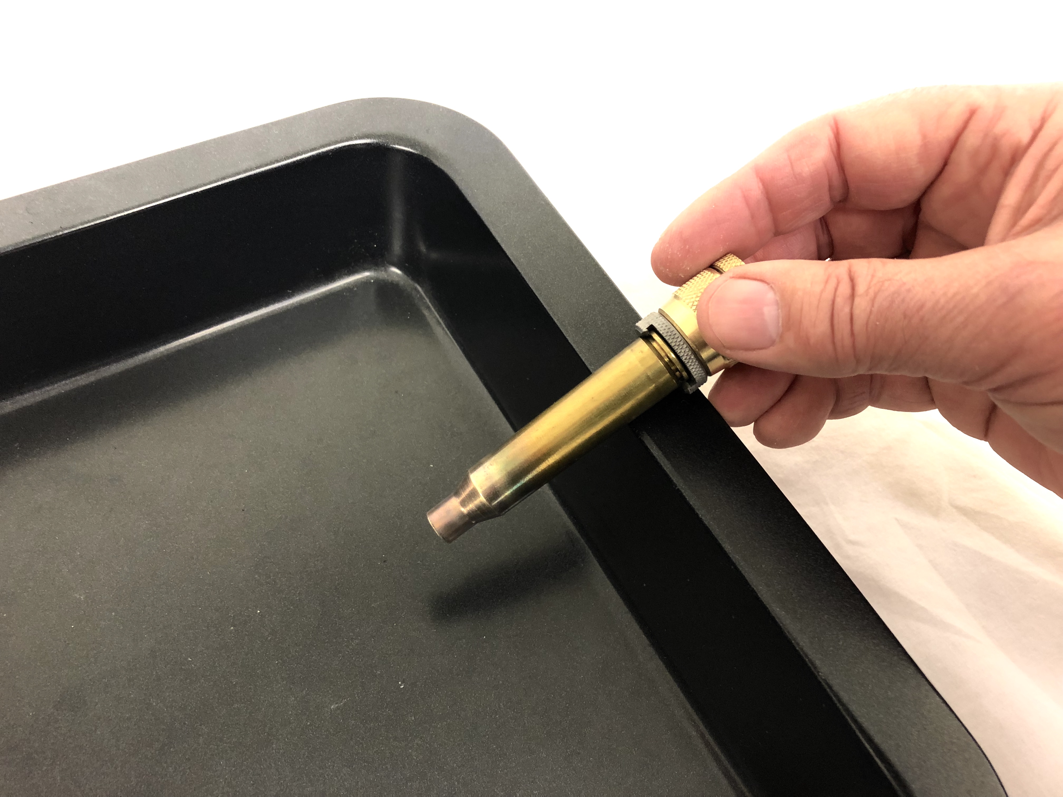
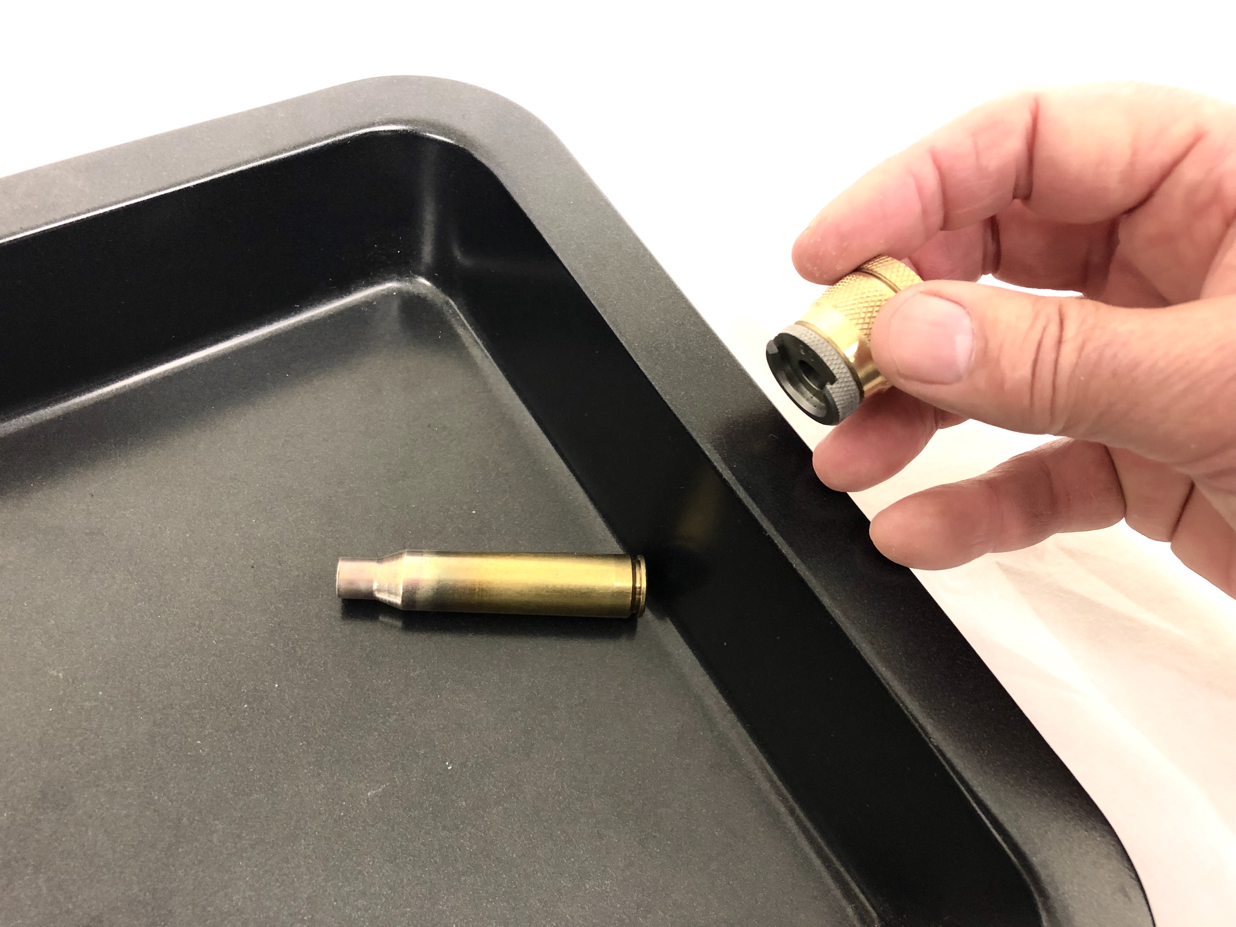
Once the annealing cycle has ended, remove the case promptly from the machine and into your chosen heat proof tray.
Take care not to touch the steel shell holder itself. That will get reasonably hot after 30 or 40 cases.
For best results let annealed cases cool down without assistance. Quenching in water is not necessary.
CASES WILL BE HOT. Take care when handling annealed cases.
When to anneal?
What is the correct sequence - anneal/resize or resize/anneal?
If annealing brass that has had multiple reloads or is unknown history, we would strongly recommend annealing first followed by resizing. This is because the harder the brass, the more likely it is to resist conforming the resizing die and "springing back".
Our settings target an annealed neck hardness consistent with virgin brass, (some cartridges are a little higher or lower). Because the process anneals both the neck and shoulder, die conformity will be correct when resizing. Note: we have found that the target annealed hardness is reached reliably regardless of the starting hardness i.e. it doesn't matter if it starts at 20% harder or even 70% harder, it will still come back to the same hardness.
If, as we recommend, annealing is done every reload, the brass is always soft enough in the neck and shoulder to resize accurately either before or after annealing. We have, however recorded consistently more uniform hardness test results by annealing before resizing, and we therefore recommend that sequence.
We find that the best results are obtained with this sequence:
- De-prime - optional depending on your cleaning sequence)
- Clean - tumble or ultrasonic etc. – again optional. Cleaning won’t affect annealing
- Anneal
- Lube - this is vital even with nitrided dies. (Imperial wax or spray such as Hornady One Shot) – note: Dry media graphite tends not to adhere well to annealed cases. We do not recommend its use.
- Resize - after annealing, THE SIZING DIE MAY NEED TO BE ADJUSTED for both shoulder bump and neck OD to account for zero spring back. See FAQ 3, 5 and 6. De-priming can be done as part of the resizing process.
For more detail, see our Annealing under the microscope articles.
Take note
Cosmetics: The appearance of different cases will vary after annealing. Some cases will show distinct annealing discoloration at the neck and shoulder, while other cases will show virtually no signs of being annealed. This is not limited to any particular brands. Do not mistake appearance for successful annealing. Some cases which appear heavily discolored may not actually be fully annealed. Our settings are reached by extensive and accurate testing of the annealed hardness.
Thermal protection: In common with any induction heater, with extended use, the output inductor will gradually heat up. Multiple fans are installed in our annealer to keep the circuitry and inductor cool. After 40 - 50 cases have been annealed, the top of the unit behind the pilot will start to feel warm to the touch. This is normal.
In the rare event that the output inductor should reach 190F/90C (inside the annealer), a thermal cut out will activate to protect the unit. If that occurs, leave the annealer turned on so the fans continue cooling. It will automatically reset after 30 minutes, once cooling is complete.
The ability of the annealer to run for the extended time depends partly on the ambient room temperature. Avoid using in direct hot sunlight or high temperature conditions. A room temperature of 70℉/20℃ or below ideal.
Our Mark ll annealer should run virtually indefinitely on programs 1 – 126 or AZTEC codes in the 0000 series (codes starting with a zero). When starting an annealing session, the fans run at 55% power. This is to minimise fan noise. An internal temperature monitor triggers full fan power if required. This trigger point depends on the ambient temperature and program level being used. For high power applications, full fan power usually starts after 50 – 150 annealing cycles. For Standard programs less than 50, or for cartridges using a comparable AZTEC code, the fans should remain on 55% power continuously.
Standard programs 127 – 200, and AZTEC codes in the 1000, 2000 and 4000 series are designed for very heavy duty annealing for cases in the WSSM family and 50 BMG. They will cycle continuously for 100 annealing cycles before automatically entering a "cool down” phase. This lasts for only 10 minutes, and then resets to allow another 100 annealing cycles.
TROUBLESHOOTING
For full support in any areas regarding how to use and maintain this machine and for any problems, questions and feedback please do not hesitate in contacting support.
There are NO user serviceable parts within the machine. Do NOT attempt to remove ANY screws
Dropped Cases: If a cartridge falls out of the shell holder and into the machine, simply turn off the power at the back of the machine, remove the pilot and retrieve the cartridge. If already annealed, it will be HOT. For extremely short cartridges, a pair of long nosed pliers can be used to retrieve them. Dropping a hot case will not damage the annealer. A small amount of poly-carbonate at the bottom of the well may melt, but this is just cosmetic. Note: our Mark ll annealers feature a ceramic insert at the bottom of the inductor. No damage at all will result from dropping a hot case.
Machine won’t turn on: Check that the power cable is firmly pushed into the power socket and check the fuse located in the power socket for serviceability. Take care to replace the fuse with the correct type (10A, 240V AC, 5mm x 20mm, F (speed), Ceramic) if needed. If the fuse is serviceable and the machine still won’t turn on contact support.
Faster than normal cut out: If the machine begins to reach thermal cut out faster than normal, check the air intake filter is clean and not obstructed as this can prevent air from cooling the inductor. The filter is located on the right side of the machine and can be removed/replaced by using a flat head screwdriver to lift the plastic cover off the outer housing by inserting it into the slots and levering outward. When not in use, we suggest placing the provided dust cover over the machine.
Cartridge over heated: Except for sacrificial cases in AZTEC mode, cases should never come out of the annealer glowing red. If one does, stop annealing and check the head stamp of the case. It will be either the wrong brand for the program setting, or alternatively, a different lot number from the samples tested for our Settings Page. If it is a different lot number, samples should be analysed in AZTEC mode or sent to us for correct Standard mode calibration. Pay particular attention to the neck wall thickness of the cartridge as this greatly effects the end result. If you are unsure of which program to use for a given cartridge contact support.
Machine operates but no heat: Ensure you have the correct program and pilot installed for the cartridge being annealed. If the above is correct and there is still no heat clean the inside of the inductor well. If any ferrous material such as steel wool fragments have accumulated, it will adversely affect the magnetics of the inductor. Cleaning with several cue tips should fix the problem. If the display screen shows FREQ DET ERROR then the inductor well should definitely be cleaned.
No annealing marks on cartridge: Please refer to the TAKE NOTE section in the previous section in the manual regarding cosmetics of annealed cartridges.
Cartridges difficult to remove from shell holder: Refer to the previous section of the manual titled TAKE NOTE it is recommended to wipe the cartridge against the lip of the cooling tray to remove cartridges instead of using fingers as cartridges will be hot.
Care and Maintenance
From time to time, debris can accumulate in the inductor air gap well. This can be removed by using a moistened cue tip or similar. If any ferrous material such as steel wool fragments has accumulated, they will adversely affect the magnetics of the inductor. Cleaning with several cue tips should fix the problem. A short spray of isopropyl alcohol down the inductor well before cleaning is helpful. Ensure the annealer is cool and unplugged before cleaning.
Stainless steel media tumbling!!
If you are using stainless steel media for case tumbling, you must be certain to remove all media from cases before annealing. If any media dislodges inside the annealer inductor well, it will be heated to a very high temperature during the annealing cycle. This will melt the bottom of poly carbonate inductor cradle and ruin the inductor. This will void the warranty. The MARK II annealer incorporates a ceramic insert which protects the inductor from SS media contamination as well as dropped cases which are hot.
The dome head machine screws used on the top and back of the annealer are blued mild steel. In damp environments, these can rust. We suggest wiping with a little gun oil periodically. The rivet heads are fine.
After use, we suggest leaving the annealer to run for five minutes before turning off. This will allow the fans to cool the annealer down and expel any condensation.
We also recommend to clean the fan filters regularly to prevent build up of dust which can reduce the fans effectiveness. The covers are held on by clips and can be removed with a flat screw driver.
After cool down, place the supplied dust cover over the annealer.
FCC Regulation
This equipment has been tested and found to comply with the limits for a Class B digital device pursuant to part 15 of the FCC Rules and as a consumer ISM device pursuant to part 18 of the FCC Rules.
These limits are designed to provide reasonable protection against harmful interference in a residential installation.
This equipment generates, uses and can radiate radio frequency energy and, if not installed and used in accordance with the instructions, may cause harmful interference to radio communications.
However, there is no guarantee that interference will not occur in a particular installation.
If this equipment does harmful interference to radio or television reception, which can be determined by turning the equipment off and on, the user is encouraged to try to correct interference by one or more of the following measures:
- Reorient or relocate the receiving antenna.
- Increase the separation between the equipment and receiver.
- Connect the equipment into an outlet on a circuit different from that to which the receiver is connected.
- Consult the dealer or an experienced radio/TV technician for help.
Using this equipment in accordance with the user's guide will ensure safe, reliable and long lasting performance.
Changes or modifications to the equipment not expressly approved by equipment manufacturer will void the user's authority to operate the equipment